
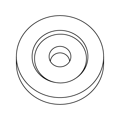
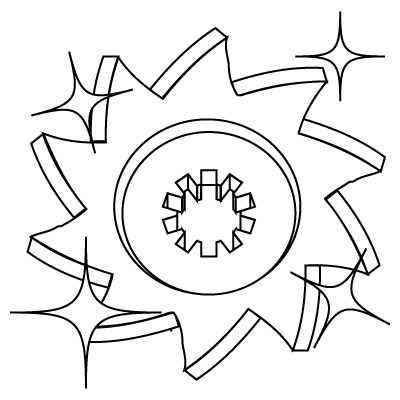
1 1. CAD Design
2DCAD or the very latest 3DCAD is used to design and simulate the blade cutting tool to match it to customer specifications.
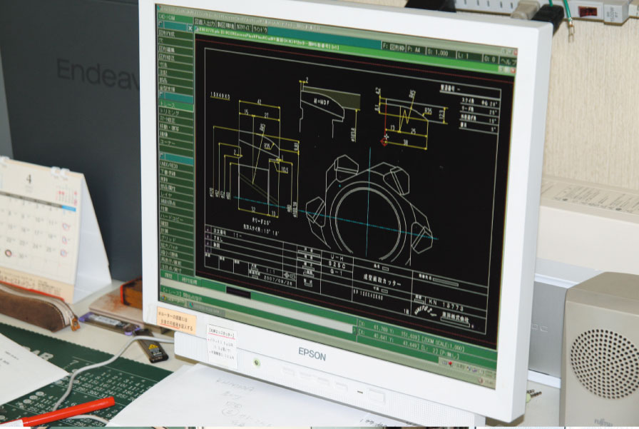
2D CAD
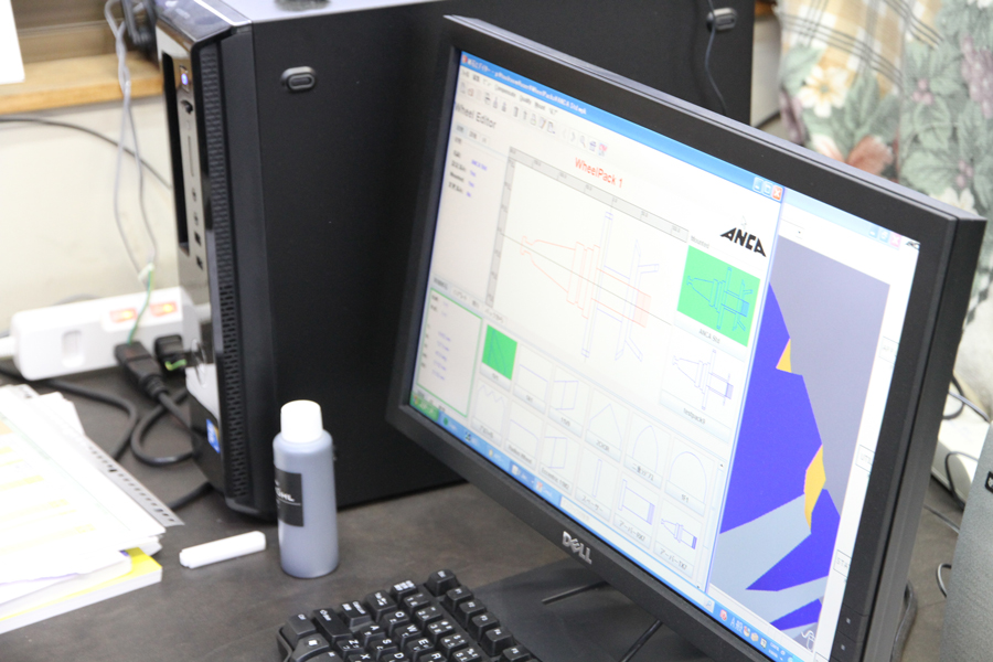
3D CAD
2 2 Cutting of Material
Round stock of the desired diameter from 3 to 350 mm is cut to the specified length by sawing machine.
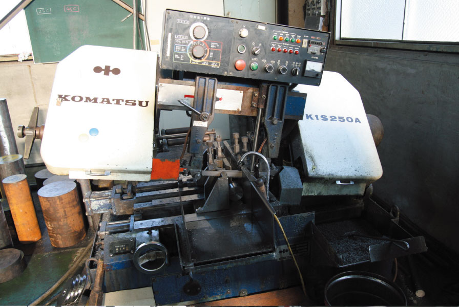
ノコ盤
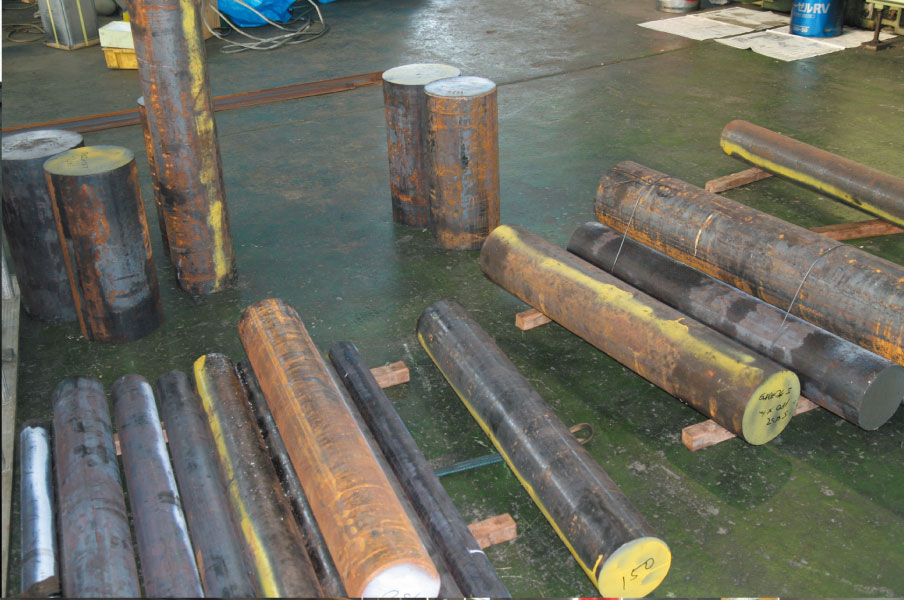
材料
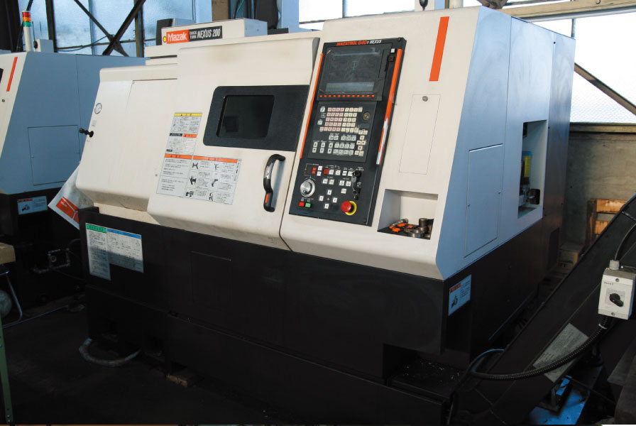
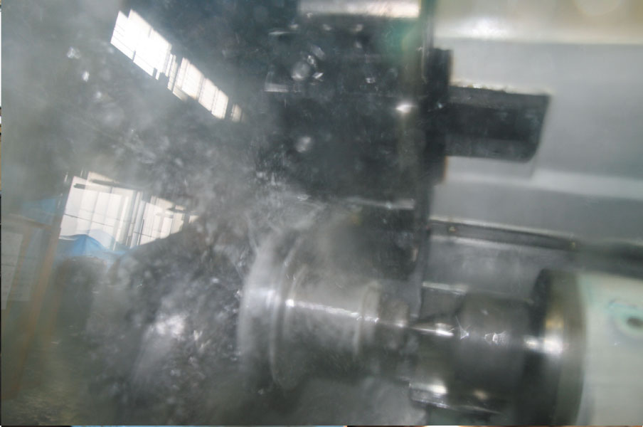
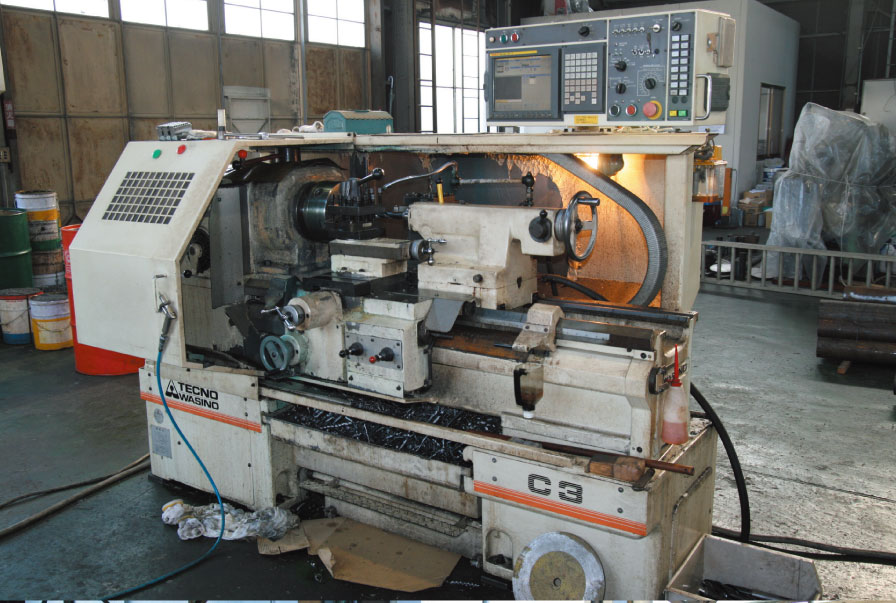
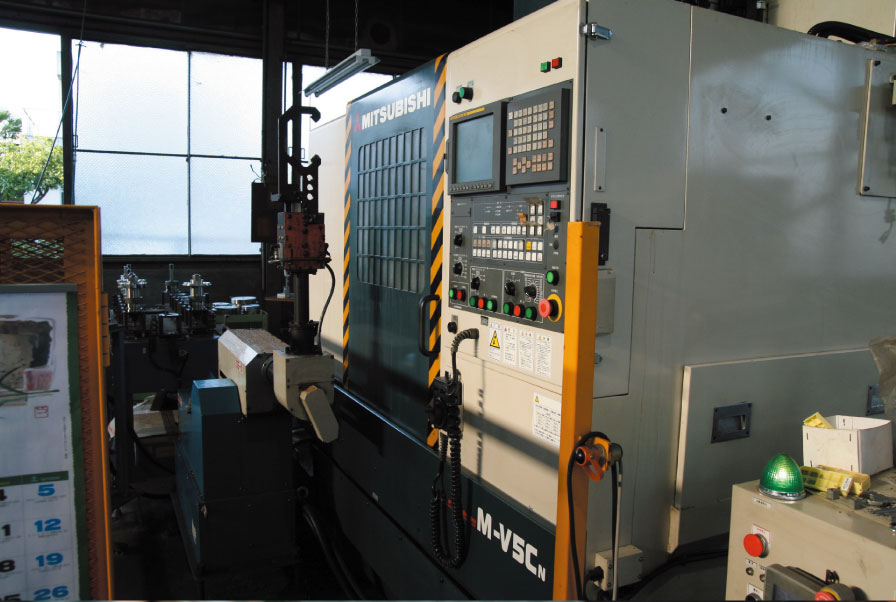
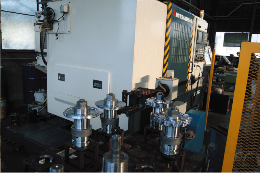
3 Machining on Lathe
The cut stock is drilled and undercut according to the customer’s design drawings.
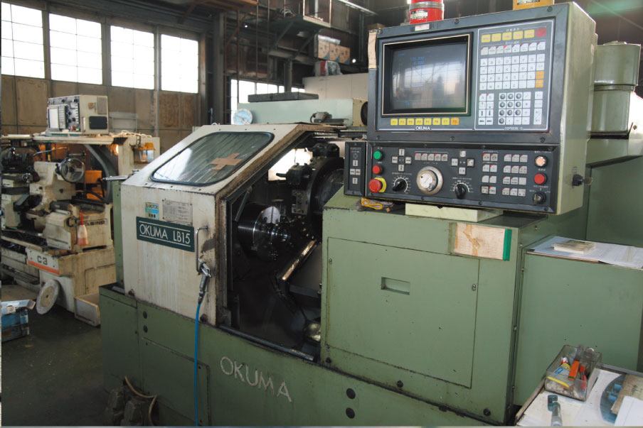
NC旋盤
NC旋盤
NC旋盤
NC旋盤
旋盤加工
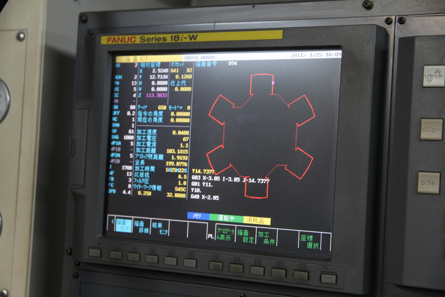
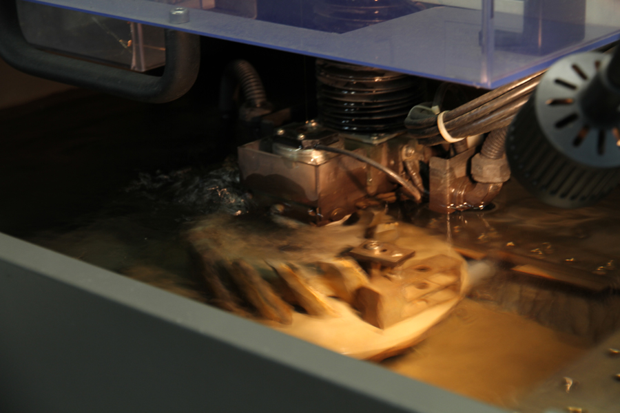
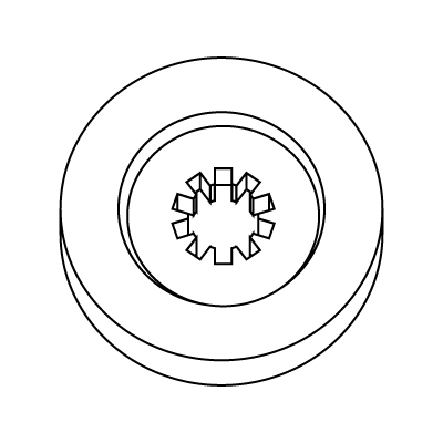
4 Wire Cutting
Wire cutting is used to cutout special shapes.
ワイヤーカット
ワイヤーカット
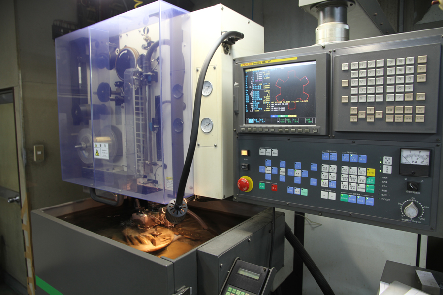
ワイヤーカット
ワイヤーカット加工
5 Milling and Other Machining
The blade is cut according to the number of teeth and angle specified in the design drawings.
This becomes the basic structure of the cutter and starts to look like a blade.
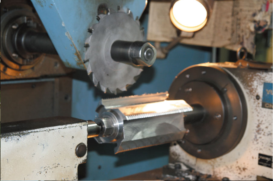
フライス盤
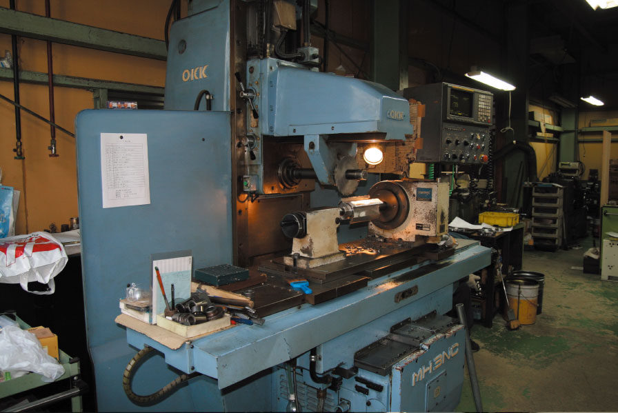
フライス盤
フライス盤
フライス盤

- フライス・マシニング加工
6 Brazing
Carbide tips and high-speed steel tips are bonded to the blade by silver solder at a brazing temperature of approximately 700°C.

- ロウ付け加工

- ロウ付け加工
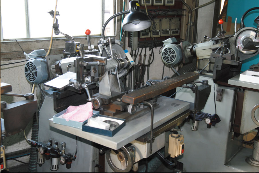
7 Finishing
The brazed tips are formed and polished to the required finish by a CNC grinder.
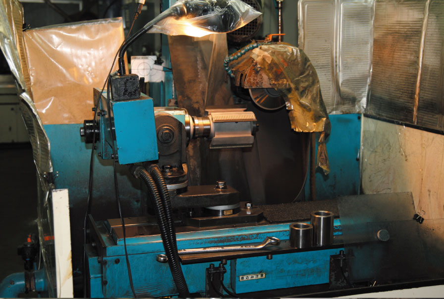
- 研磨機

- 研磨機
- リュウメン刃付機
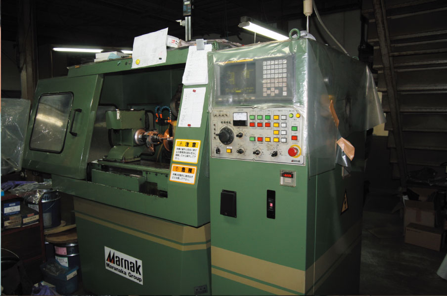
- プロファイルNC研削盤
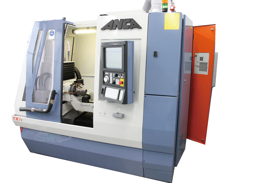
- ANCA
- 仕上げ
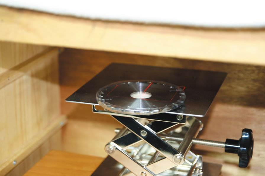
8 Inspection
Dimensions and shape are checked by a balance and projector.
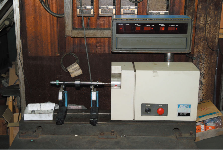
- バランサー
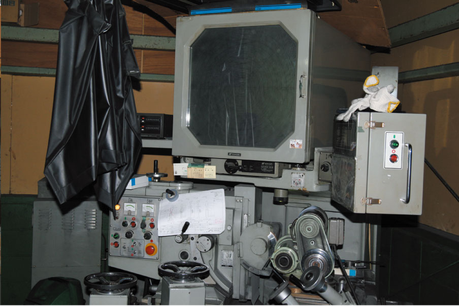
- プロファイル研削盤
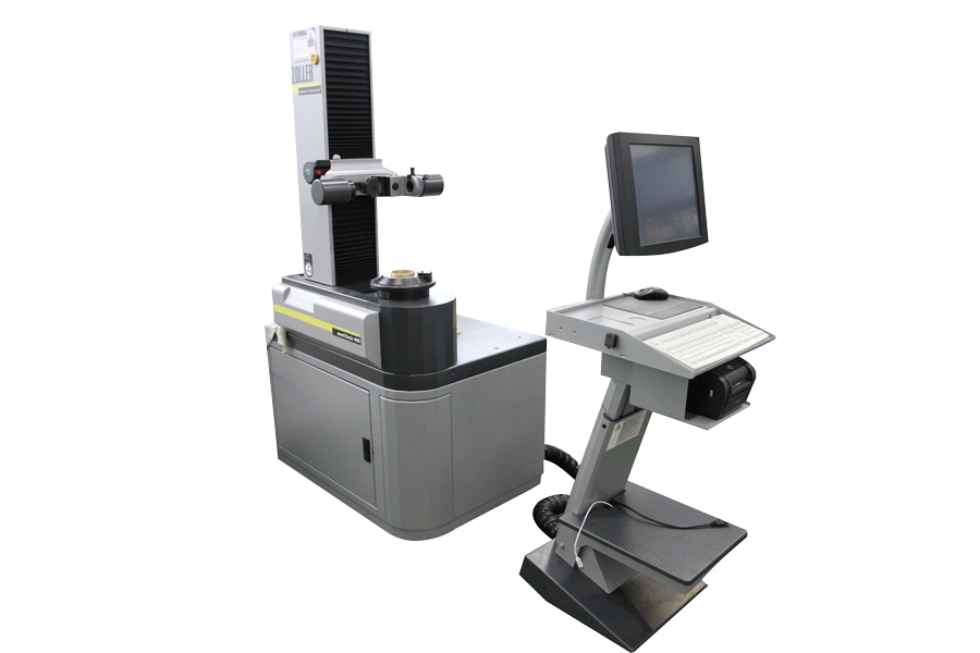
- zoller
9 Laser Marking
Cutters are inscribed with dimensions or marks specified by the customer by laser.
- レーザーマーカー

- レーザーマーキング